
In this part, I want to log on building the display board. Let’s start by unboxing the kits.
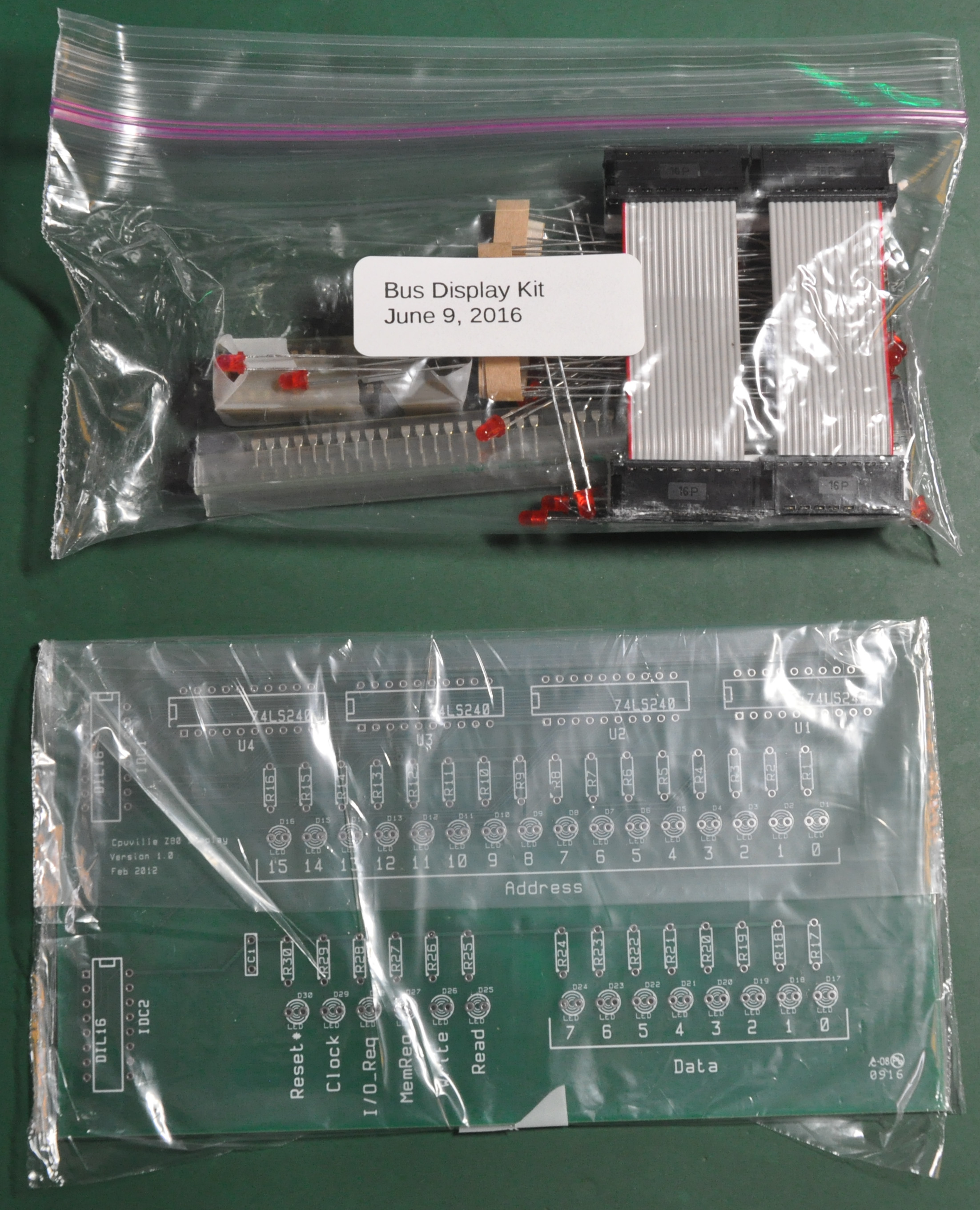
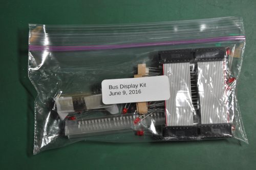
As usual, the kits is packed well in the Ziploc bag.
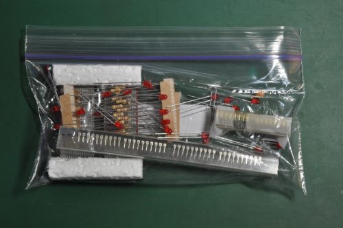
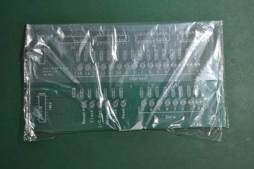
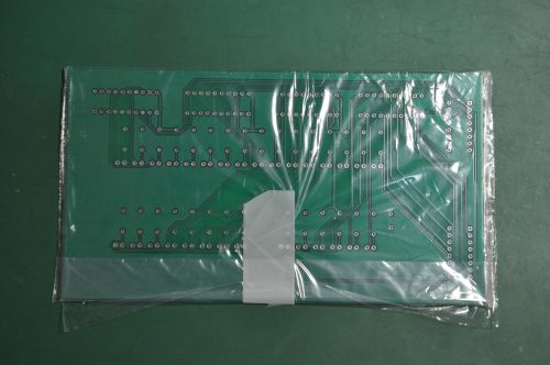
Let’s do the unboxing.
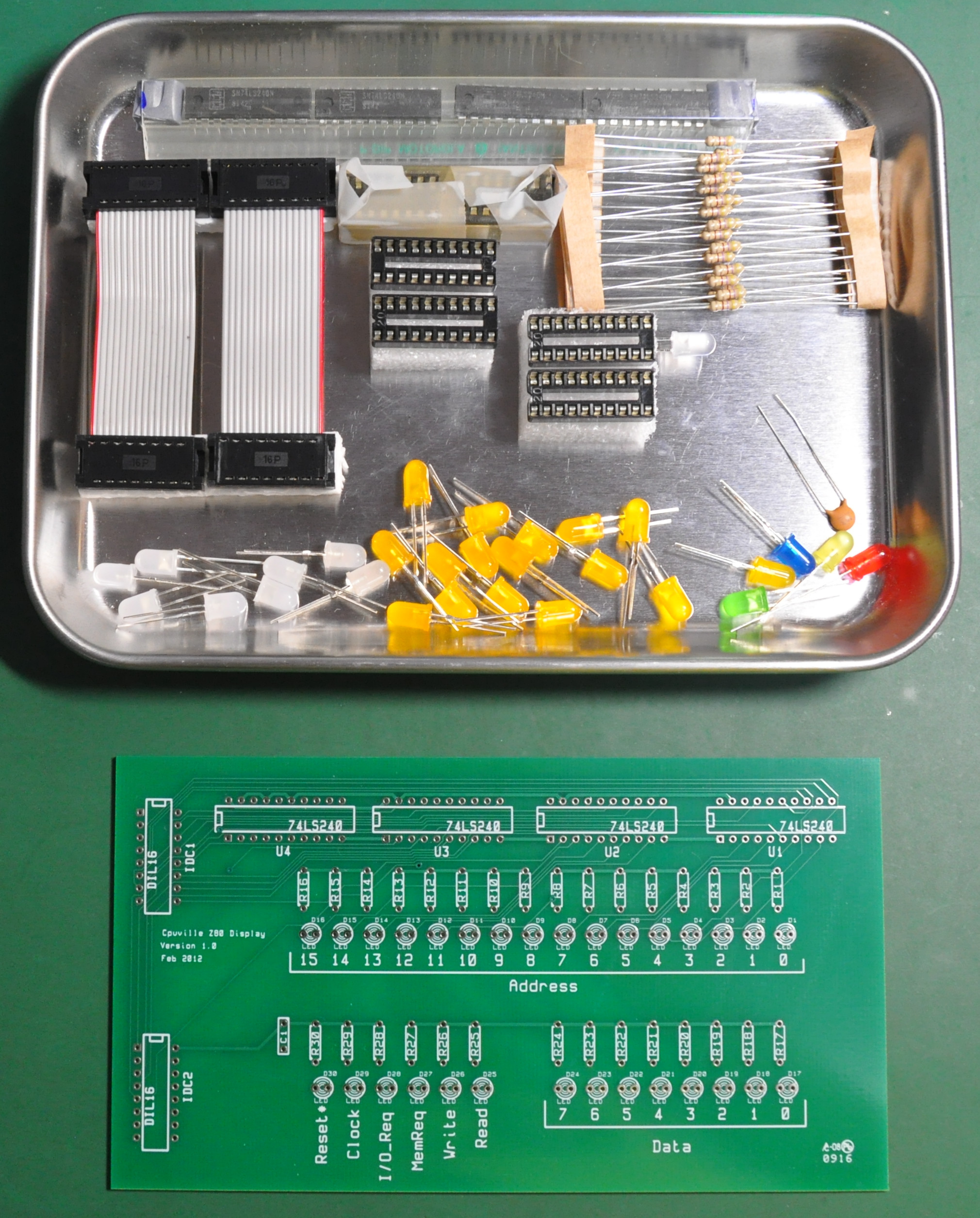
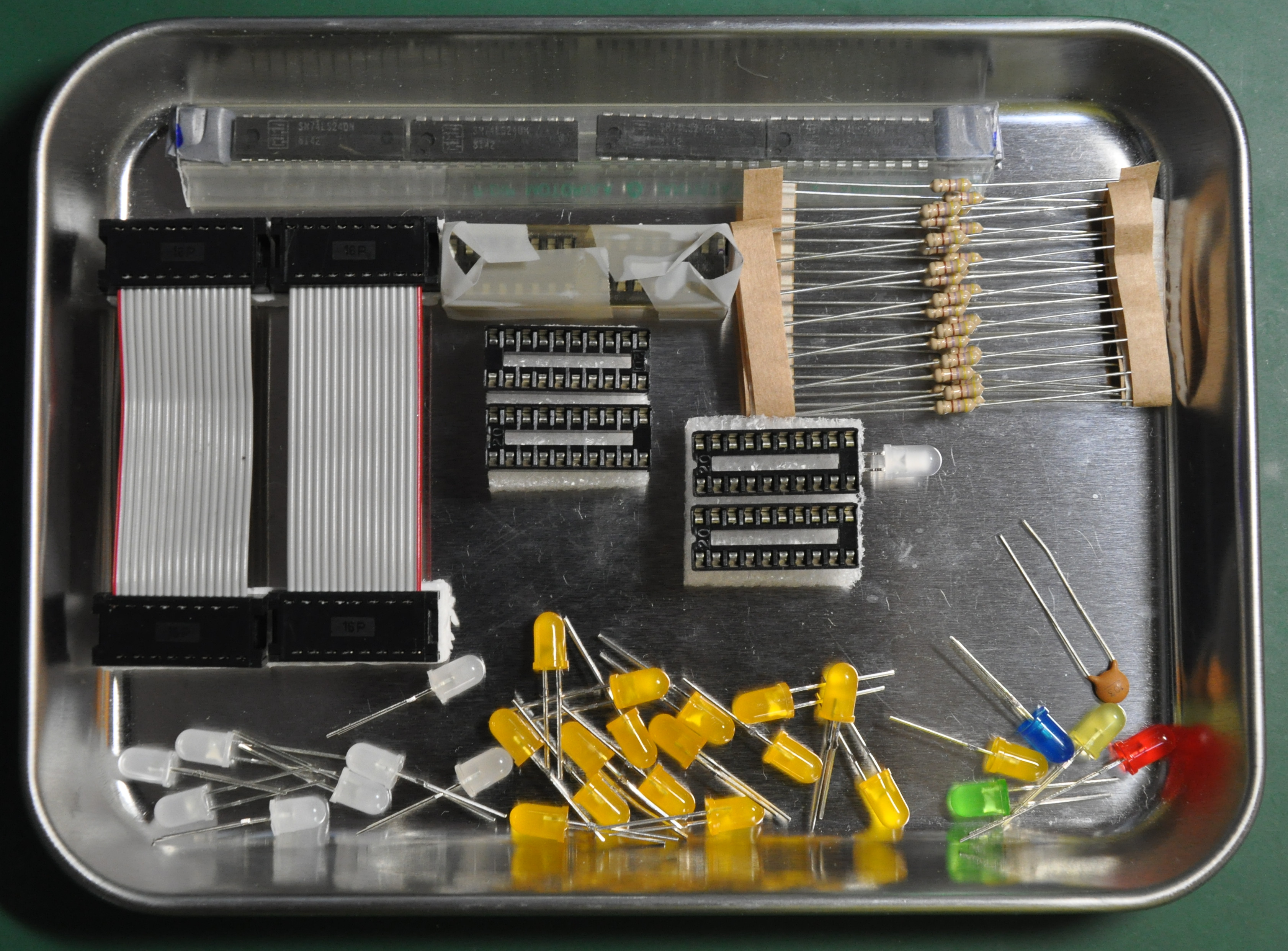
It looks like all the components are there, and the board is very straight forward to assemble. Please note that I have replace the LED to my own favorite colors to make it look nicer. I also add 4 IC socket as the seller of this kit doesn’t include any socket for the ICs. I think it would be nice to implement the ICs with the socket in case I will burn those ICs in the future.
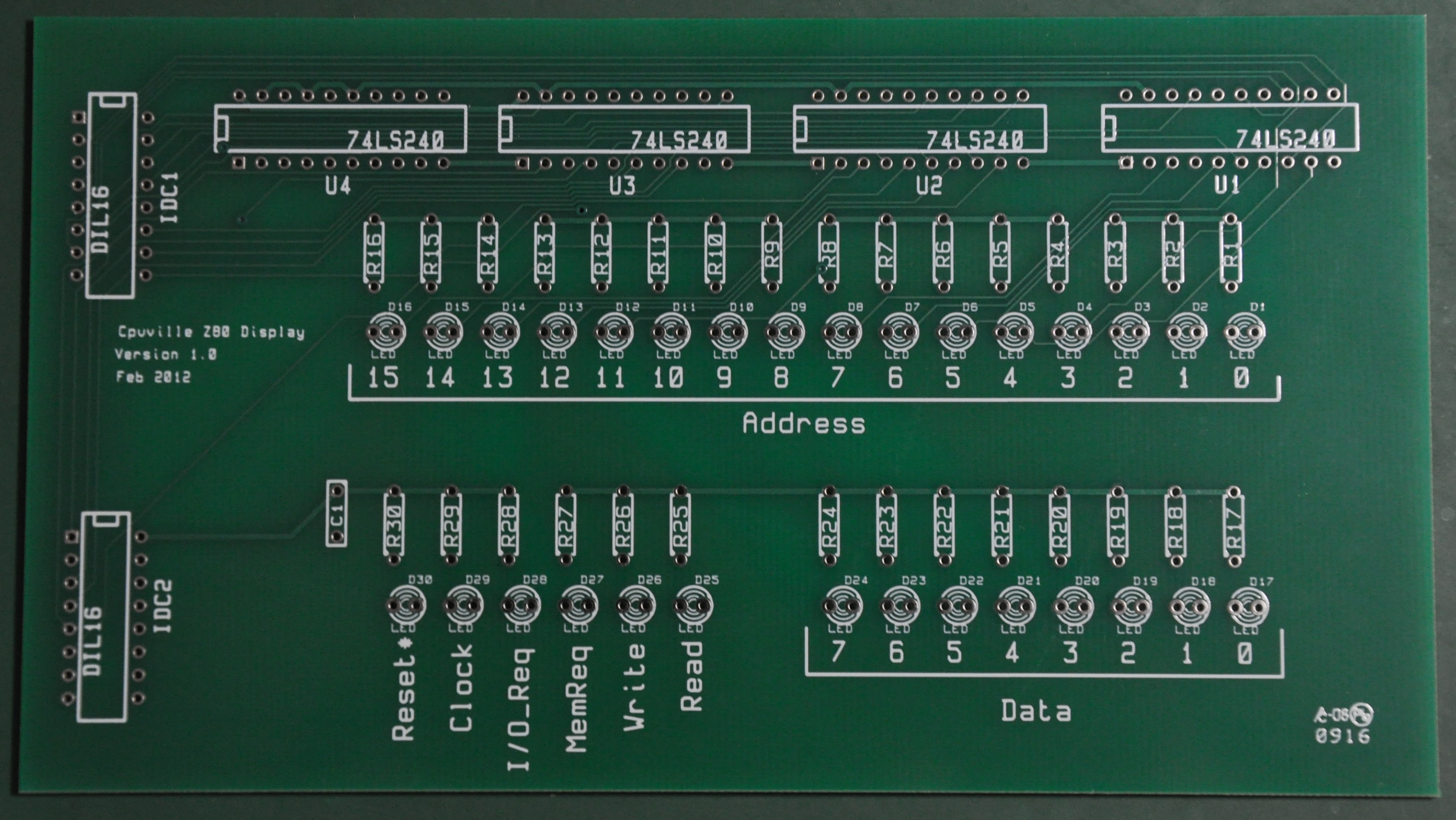
The PCB looks very nice and well fabricated. The soldering process is also very smooth, solder will move along into the hole with component lead. Sometimes it will have some cold solder but it is not too hard to fix the problem. Just feed the heat and solder, but not too much heat, especially to the LED lead.
Now it’s soldering time !
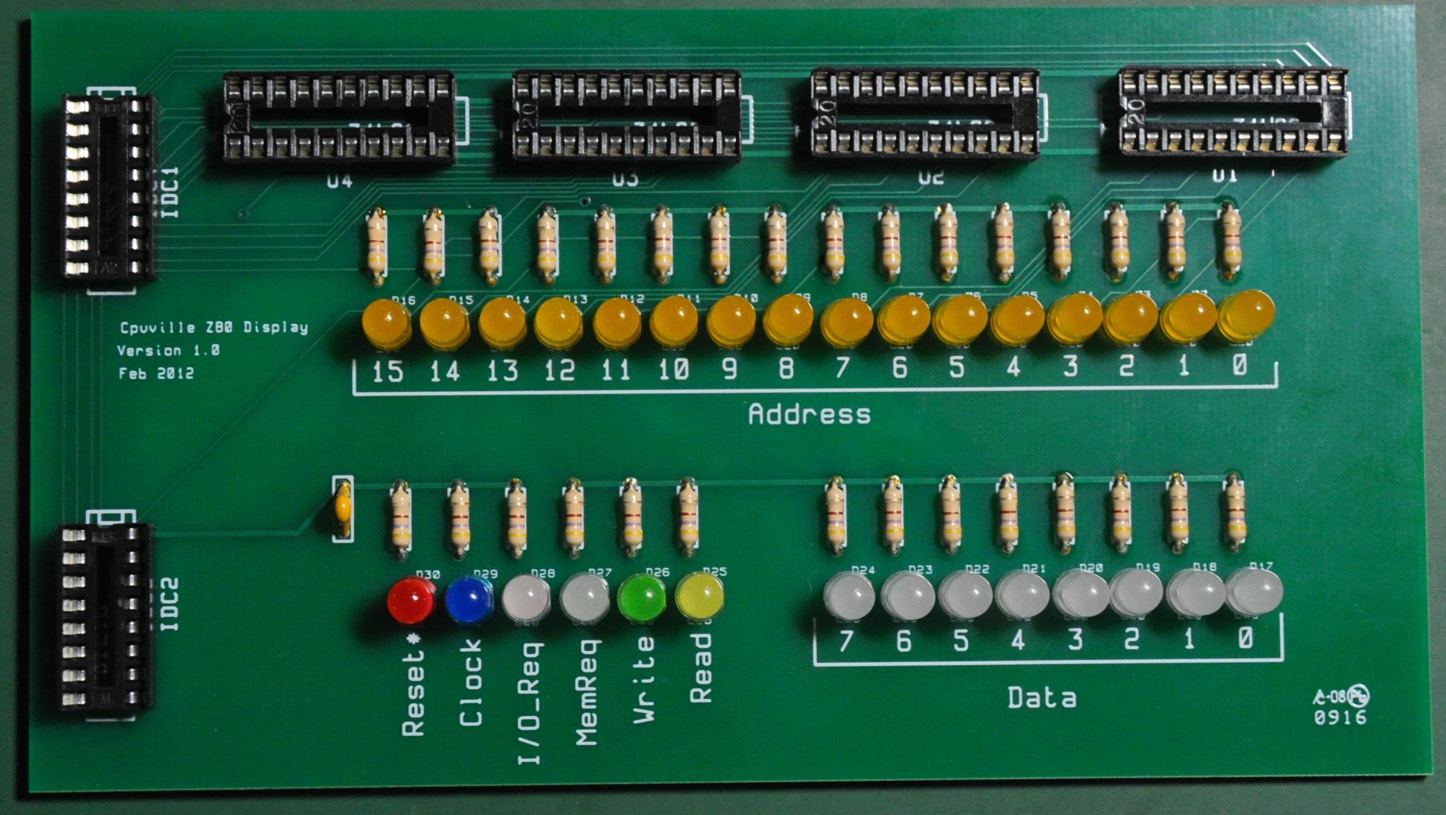
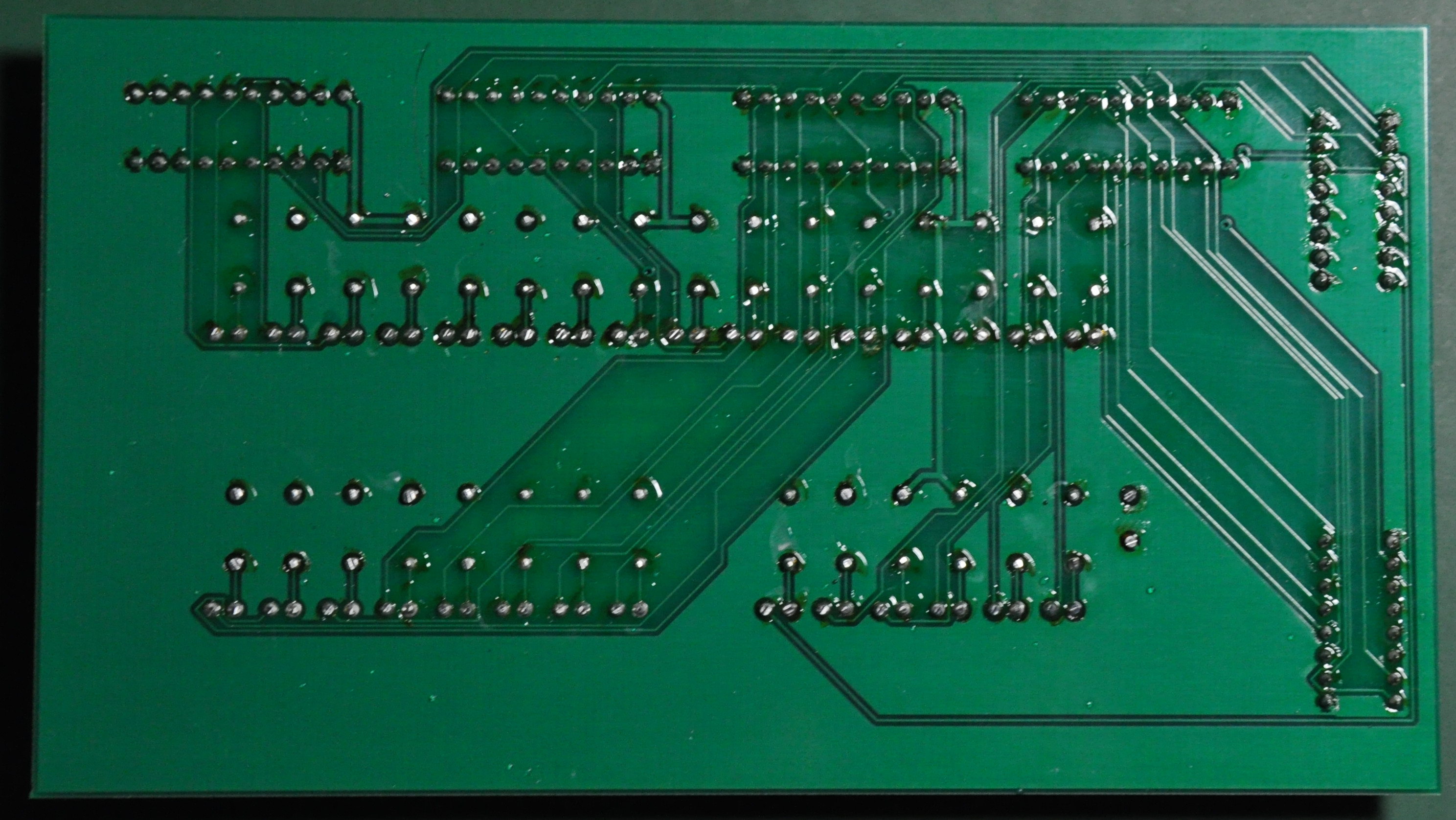
Above is the finished board. The IC socket is not included in the kit so I use the socket from my own parts inventory. I also customized the LEDs so it will make it look nicer. At the left is the bottom part of the board. It is easy to solder with this board. The solder will flow smoothly. The next step is to clean the flux and implement the ICs.
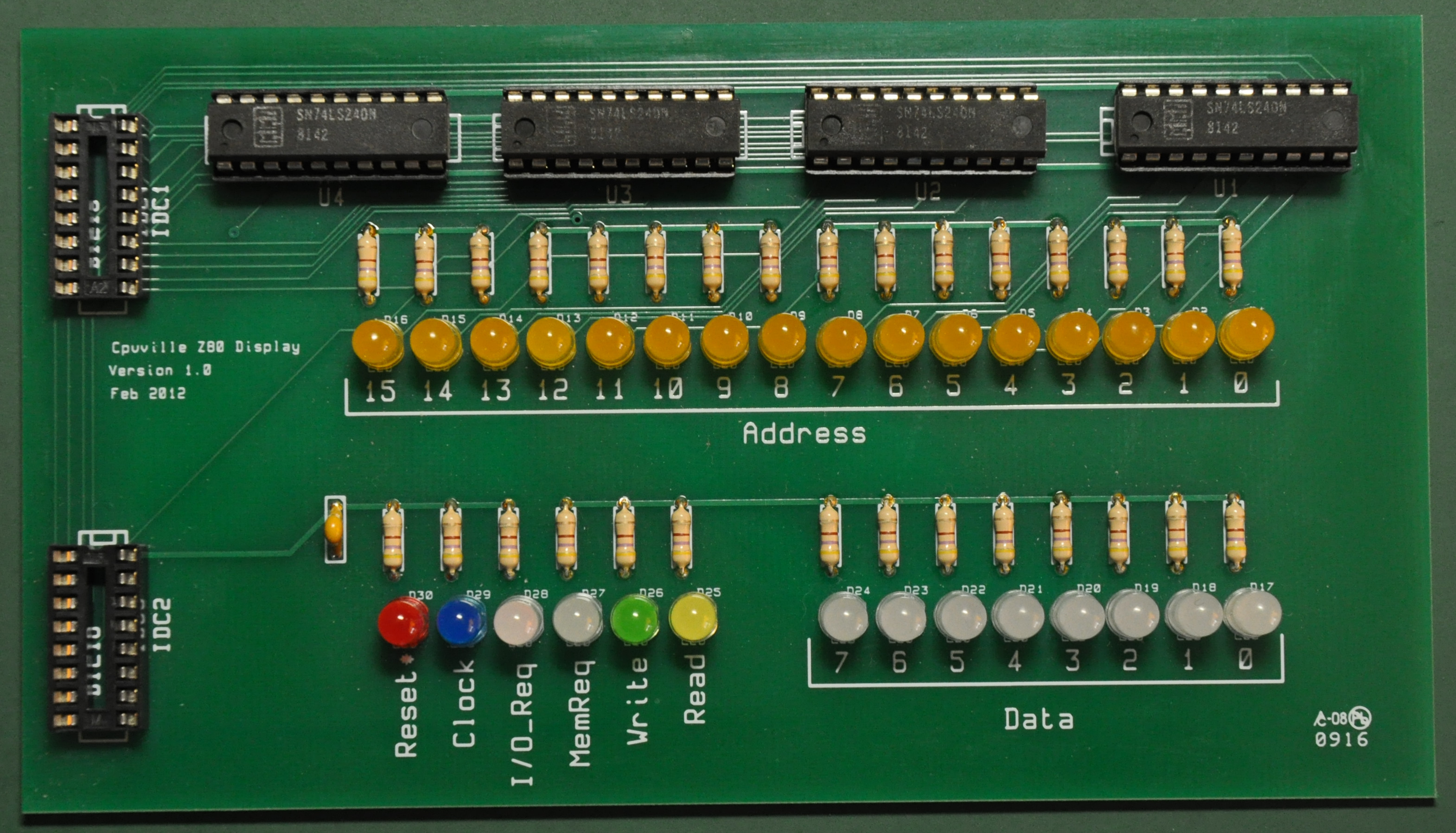
Here is the finished board with all the ICs implemented.
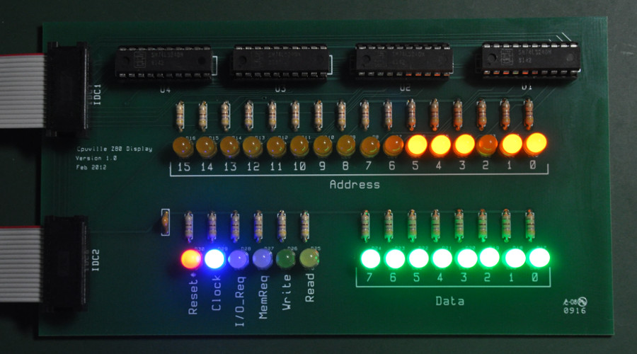
Now it’s the time to connect to the Computer Board and run some tests.

Above is the test run picture.
It is running the ‘Count to Million’ program that resides on address 0x0032 in the ROM with the slow clock mode. Those LEDs looks great !
Here is some program that we can load to test the bus display board
Count to Million 0x0032 (00000000 00110010)
Simple Counter 0x002A (00000000 00101010)
