I have lots of junk parts around and I found a 8255 PIA ic in my junkbox. In the meantime, I am in progress on learning z80 assembler and want to learn on how to control the I/O via the PIA. So I decide to recycle the PIA and make a PIA module for my rc2014.
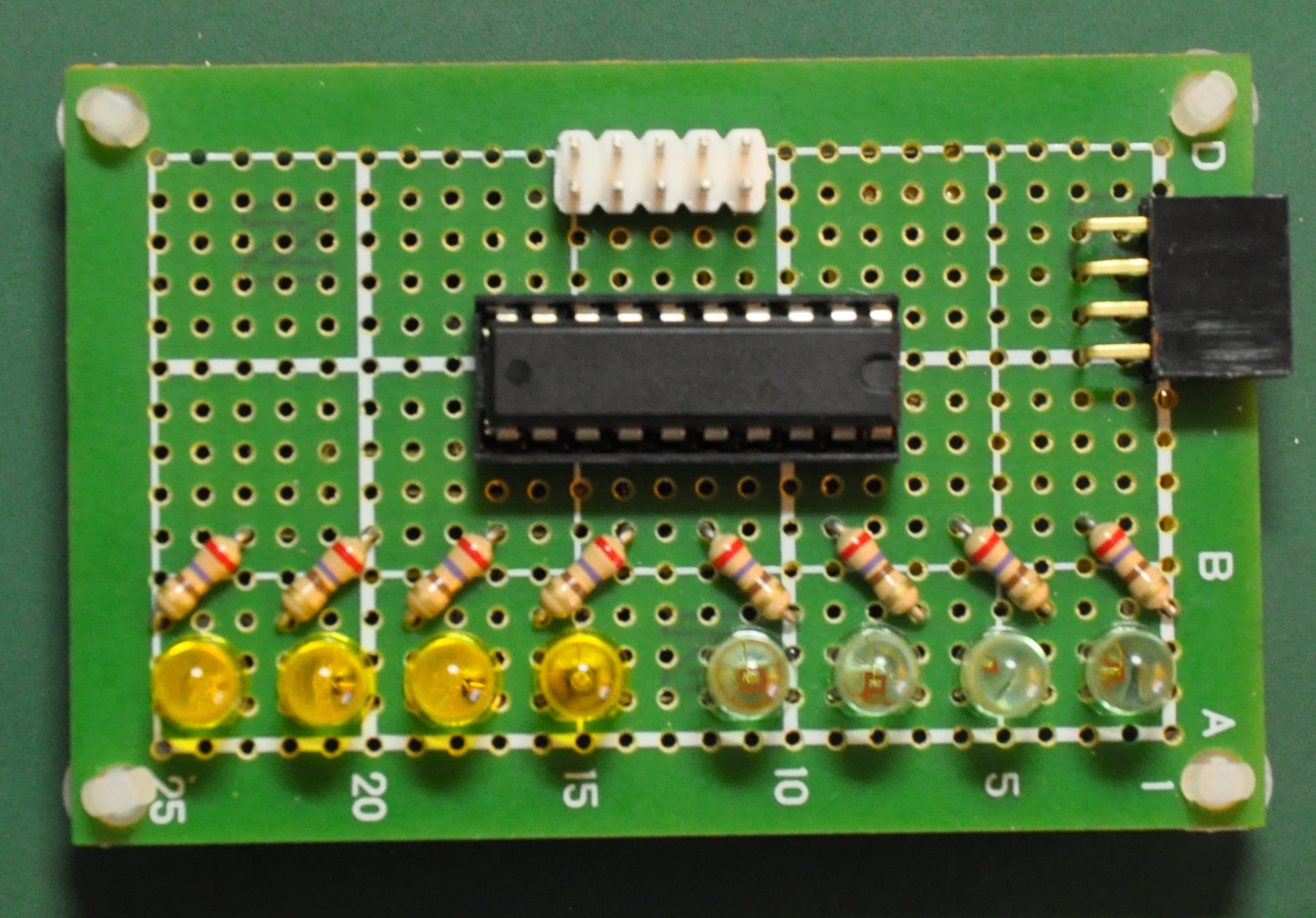
The PIA Module Board
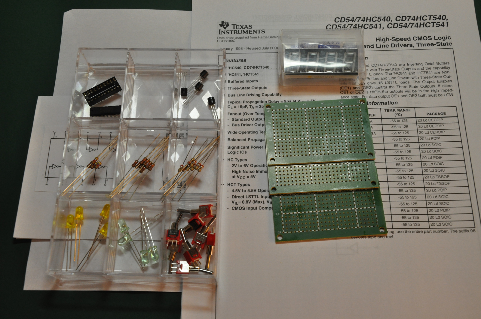
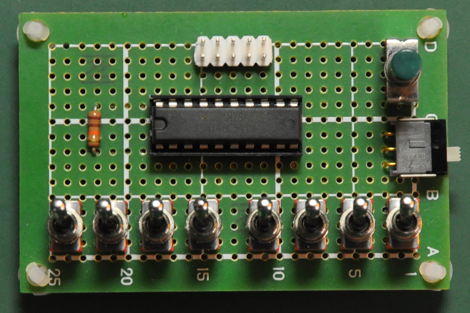
I used the prototype pcb that I bought from the seller of the rc2014 at tindie. As I look around I found that the space on the proto-pcb is limited. The creator of this pcb has put a trace in the middle and some vertical trace on each pins. That’s make the protoboard use limited. So, I just decide to solder all the needs components and wire up with small AWG30 wires. I use two different colors of the wire to make the wiring easier. I use the 74LS688 magnitude comparator for the address decoding. The recycle chip is OKI M82C55A-2.
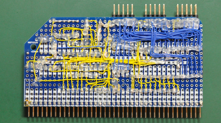
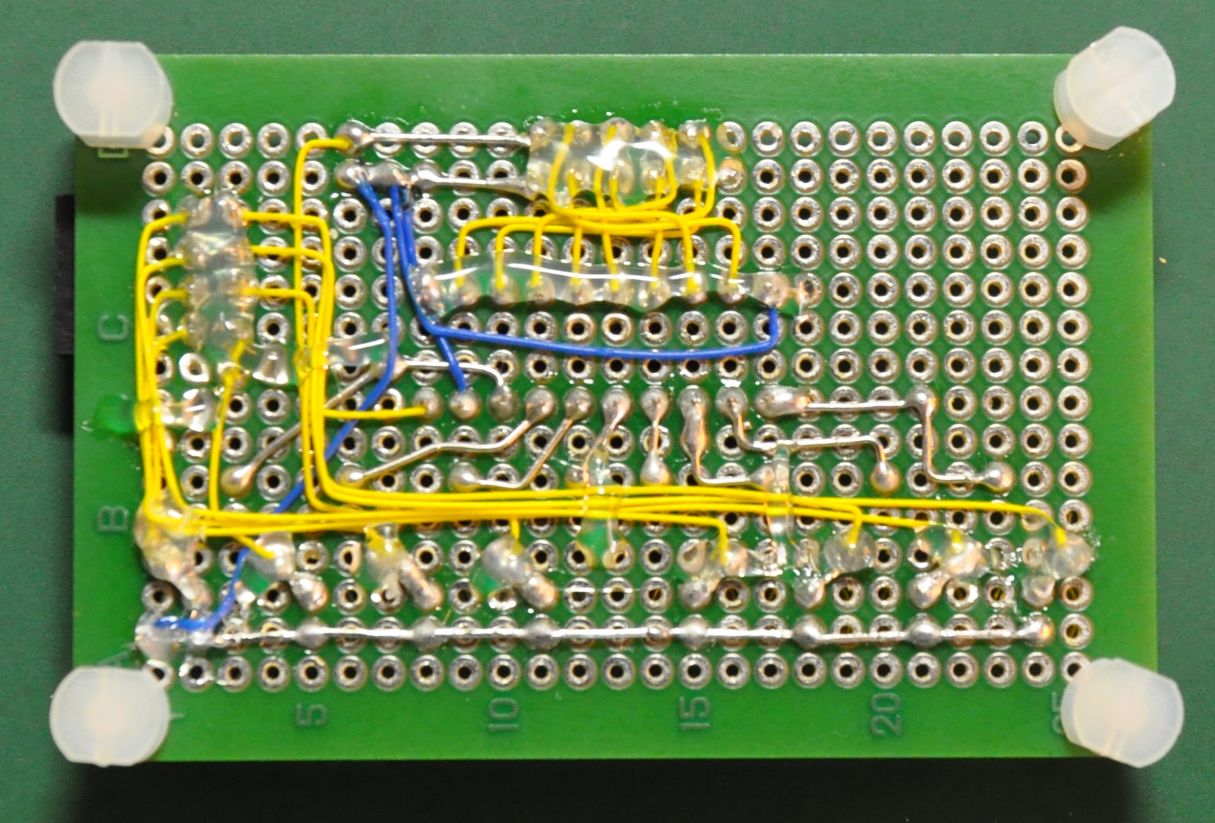
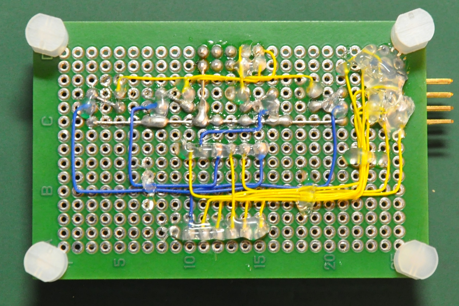
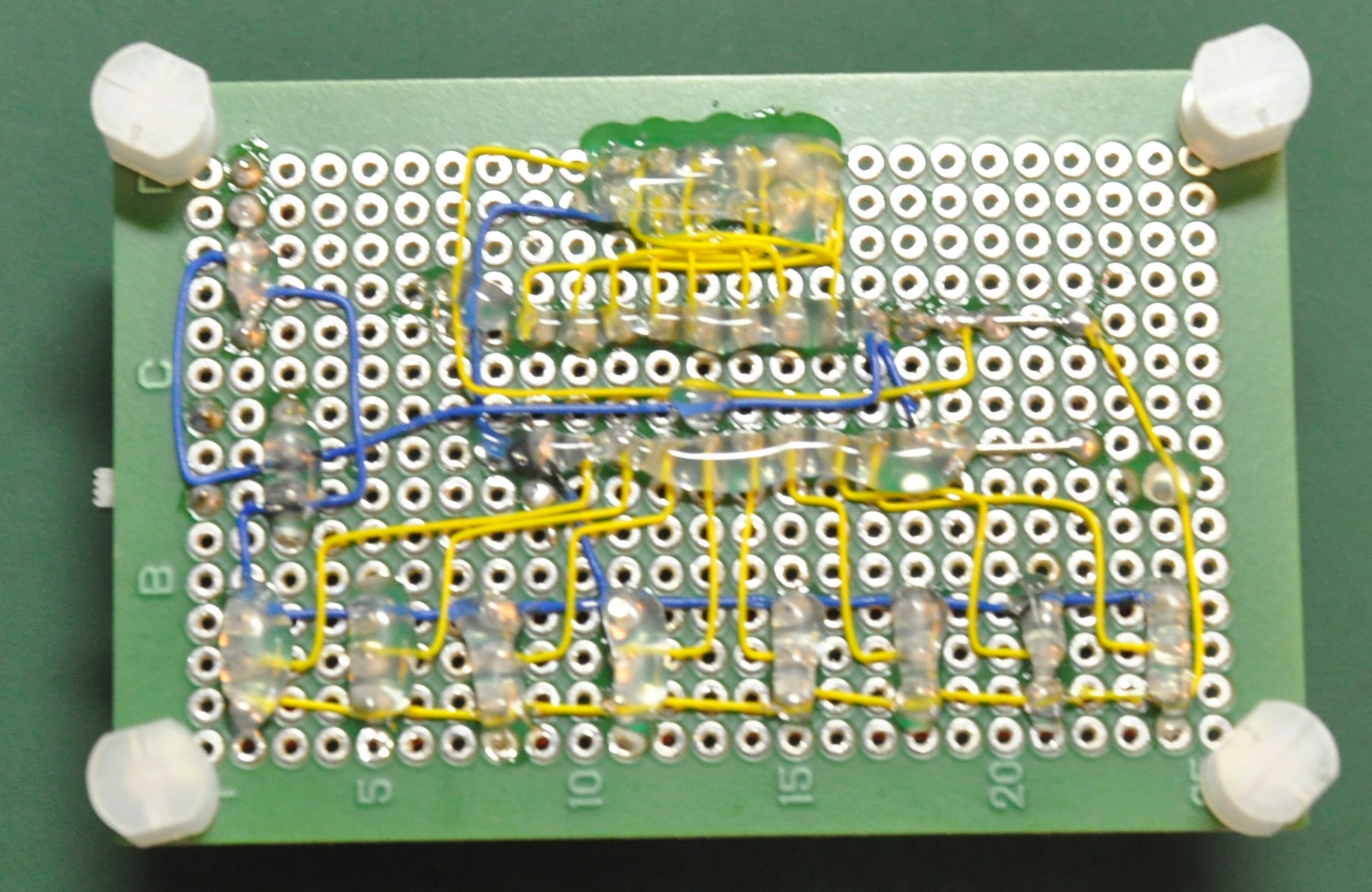
Here is the back side of the board. I took some time to route the wires nicely. After I confirmed all working, I put some hot glue on the solder part of the wire so it will not easy take off.
I have set the board to be at address F0h, so Port A at F0h, Port B at F1h, Port C at F2h and setting register at F3h. We can change the address to what we want within the I/O available addresses.
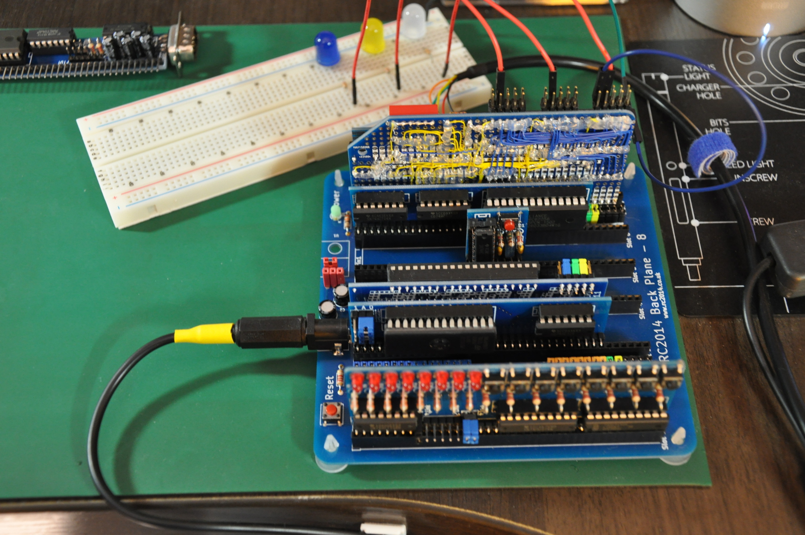
Here is the picture when I testing the module. I put three led’s for testing those three ports and it work fine. Overall, I am very happy with the result and I also very happy that I have recycled a 8255 for use in my learning process.
I/O Training Board
Here I have made an I/O training board for use with above PIA adapter.
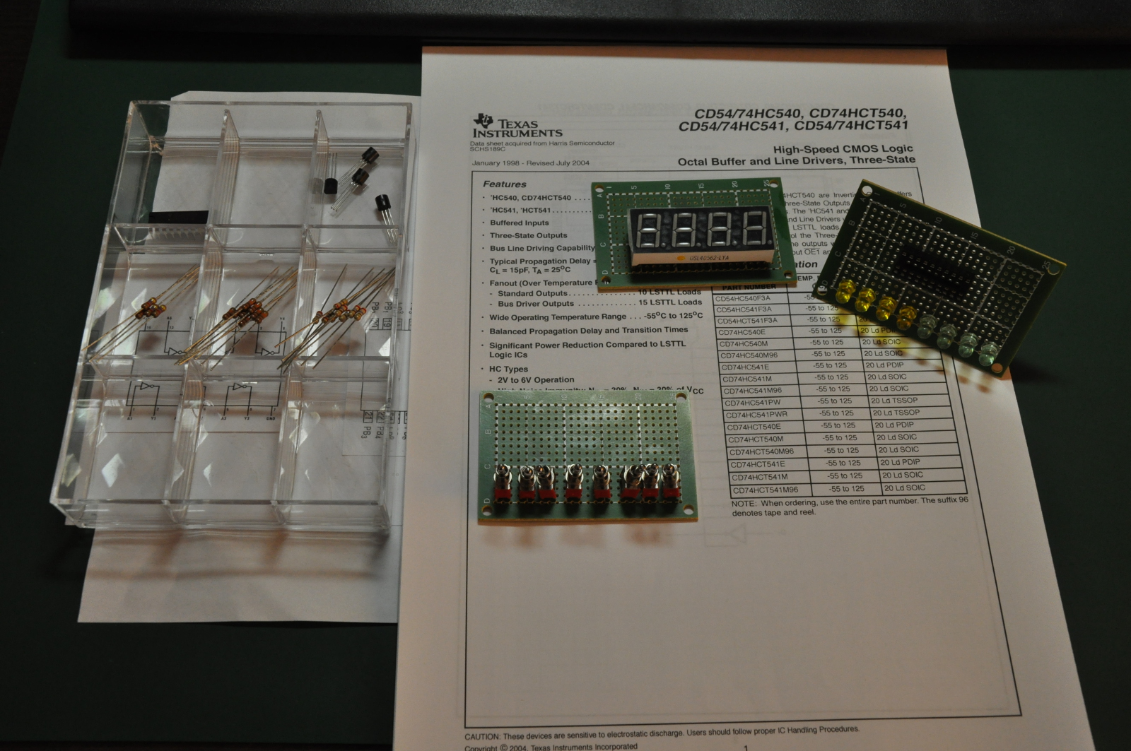
This modules include 8 led’s, 4 digit 7 segment display (common cathode) and 8 input switches. All this boards are for use with those Port A, Port B and Port C.
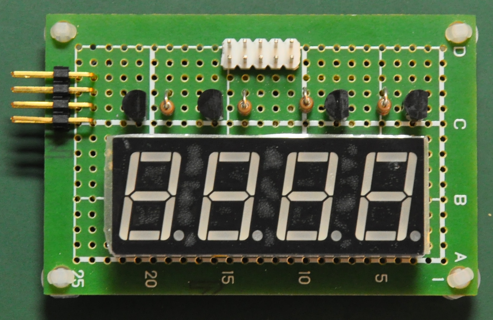
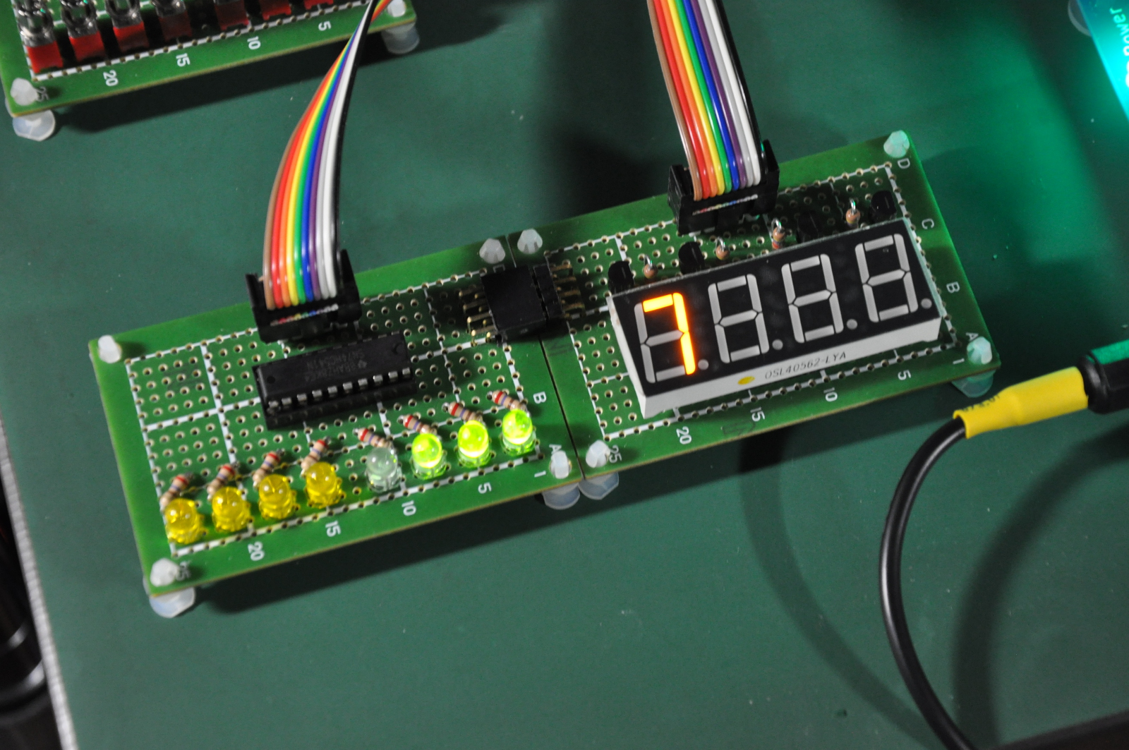
The 4 digit 7 segment display is driven with 4bit line, the 7 segment itself is driven with 8 bits port from the led board. To light up the display just set the segment to light up, put lower 4 bits of the port connected to the display to select which digit that we want to display. For example,we have connected the 7 segment board to port B and the led board to port C, and we want to display number 7 on the very left digit of the 7 segment display. So here what we need to do:
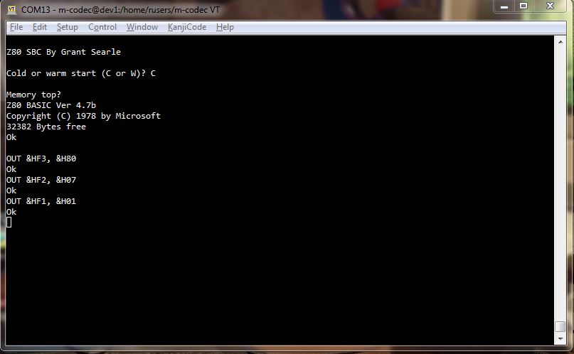
- Set the setting register on address F3h to 80h, that means we want to use those 3 ports as output mode.
- Set port C register on address F2h to 07h to display the number 7.
- Set port B register on address F1h to 01h to display the very left digit of the 7 segment.
That’s all. Now we can see the number 7 on the very left digit of the 7 segment display. Note that the led on the led board is also lid up, the led’s are presenting the 7 segment decode bit.