
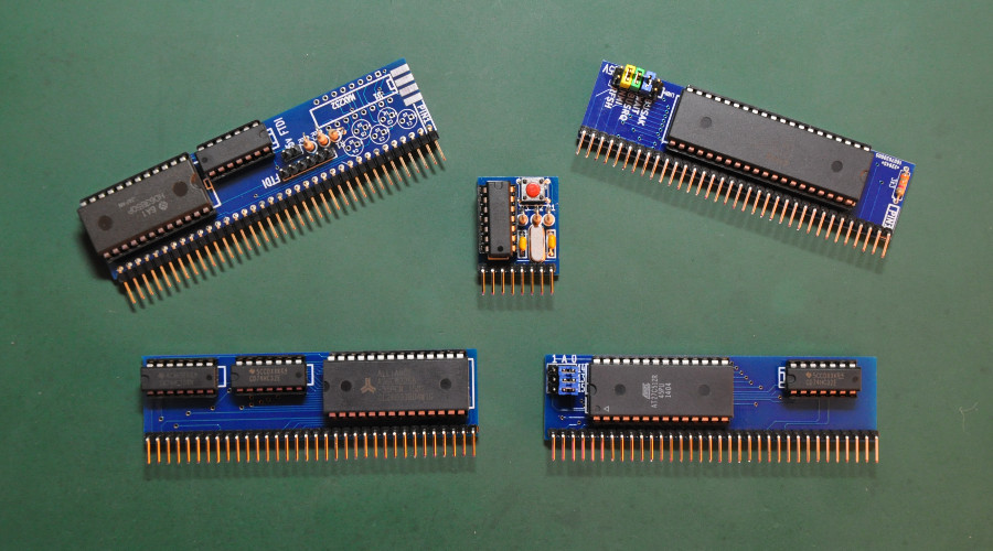
On this part, I wan’t to log the build of base boards for the RC2014 Z80 computer. It’s included those boards to be build :
- Clock (7.3728 MHz)
- Z80 CPU
- Selectable ROM (divided to 8 by jumper, 8k each)
- 32k RAM
- Serial I/O
Those module boards are needed for the rc2014 computer to operate in minimal settings.
Let’s get stared !
Clock Module
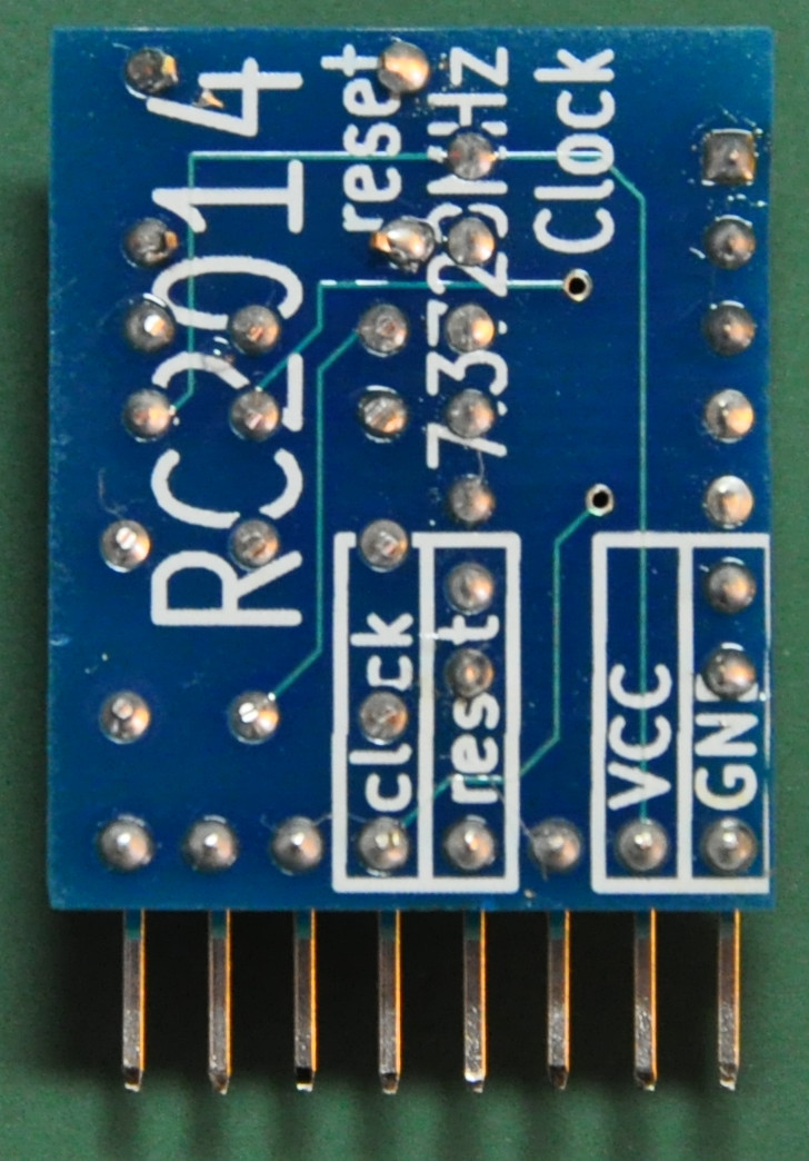
This is the clock module for the RC2014. It use the 7.3728 MHz crystal oscillator. Let’s start by checking the pcb board and components included.
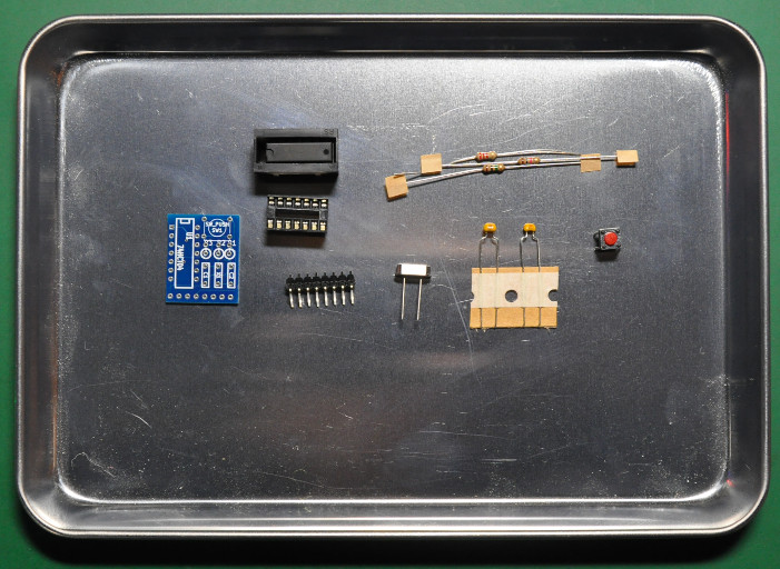
It looks very simple, just few components that needed to be soldered, lets look at the pcb board.
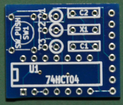
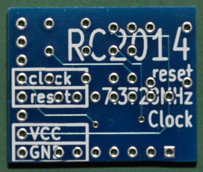
As usual, a very nice pcb and it is very small ! Time to go for soldering.
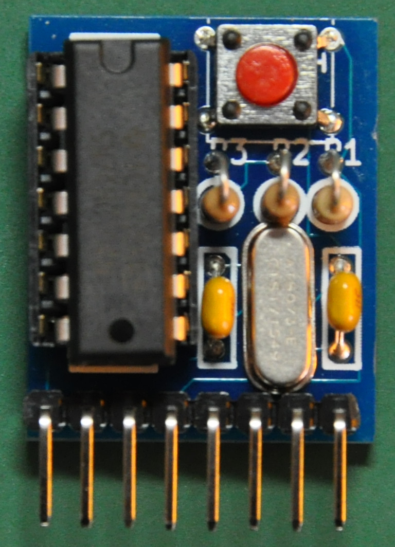
Above is the finished board, I have cleaned up the flux and the board is ready to use. The seller of this kit didn’t provide the reset switch, there is a footprint on the pcb for the reset switch so I have added the reset switch from my own parts inventory, tought that it will be useful later.
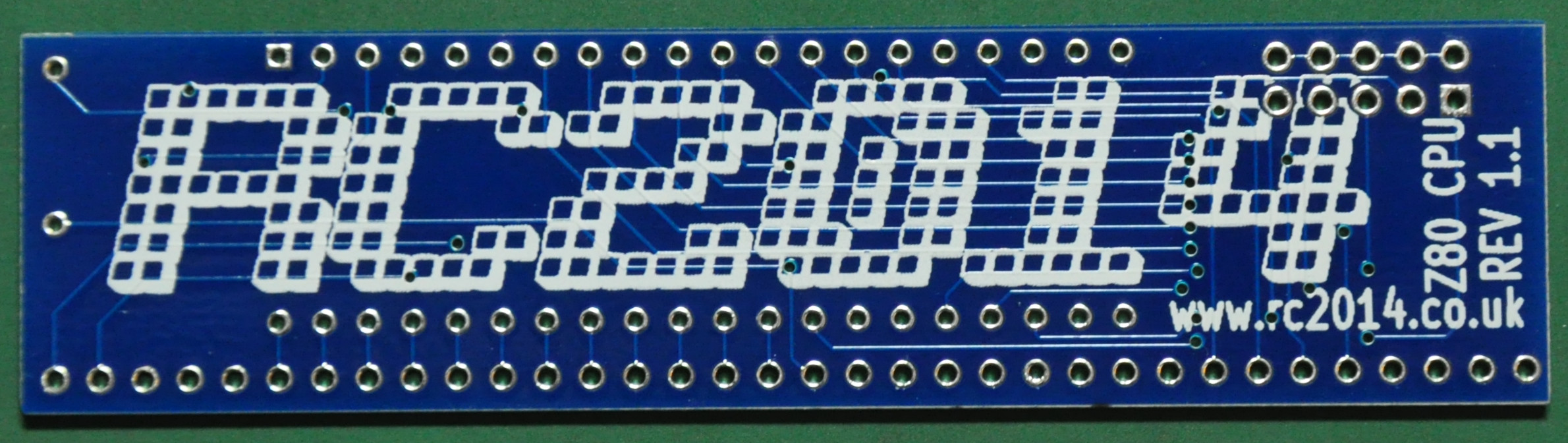
Z80 CPU Module
From here, assemble the cpu module. As usual lets take a look at the board and components that provided with the kit.
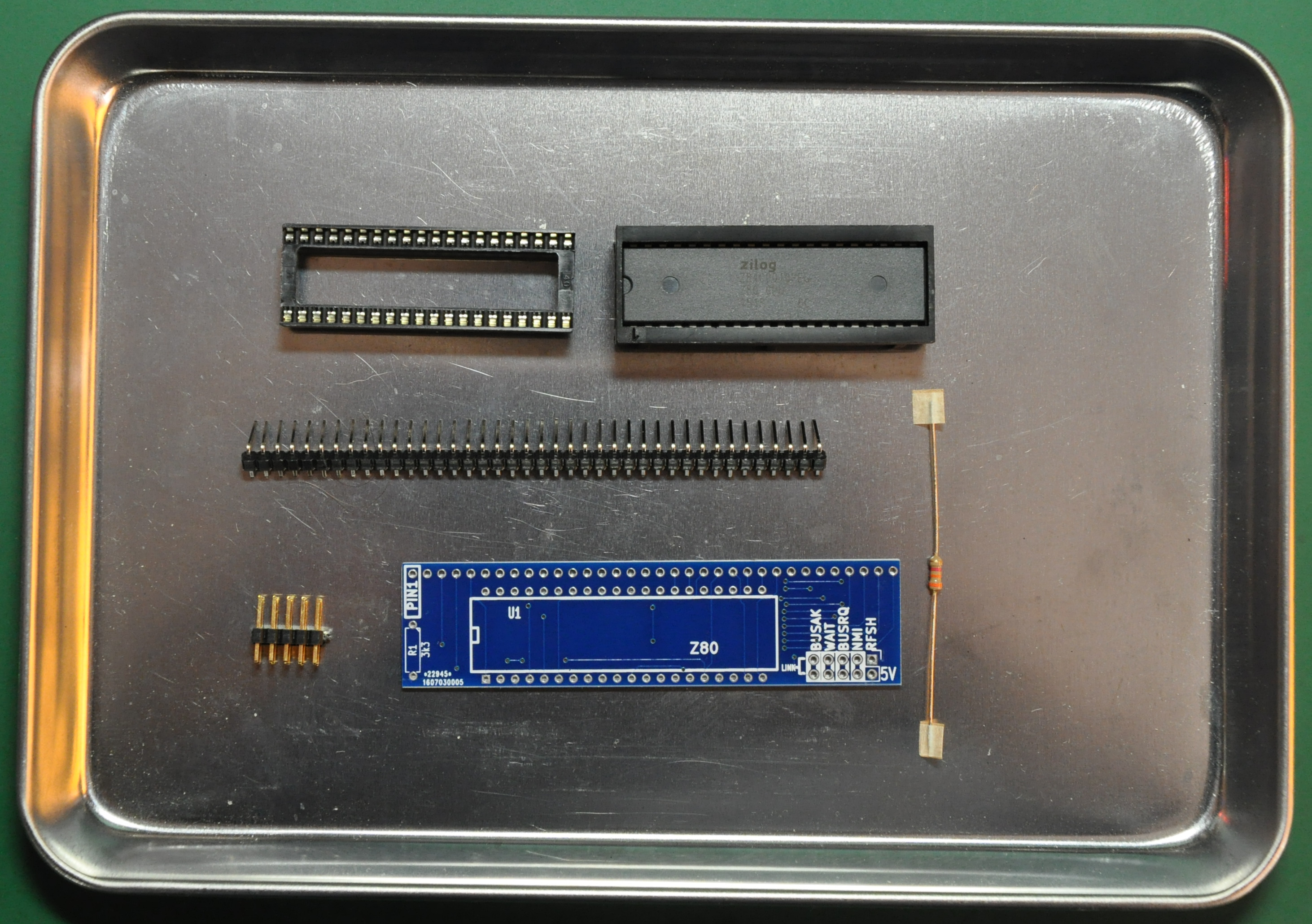
The components are just the pcb, socket, header, one 3.3k resistor and the cpu itself. The 3.3k resistor is the pullup resistor for the interrupt (INT) pin.
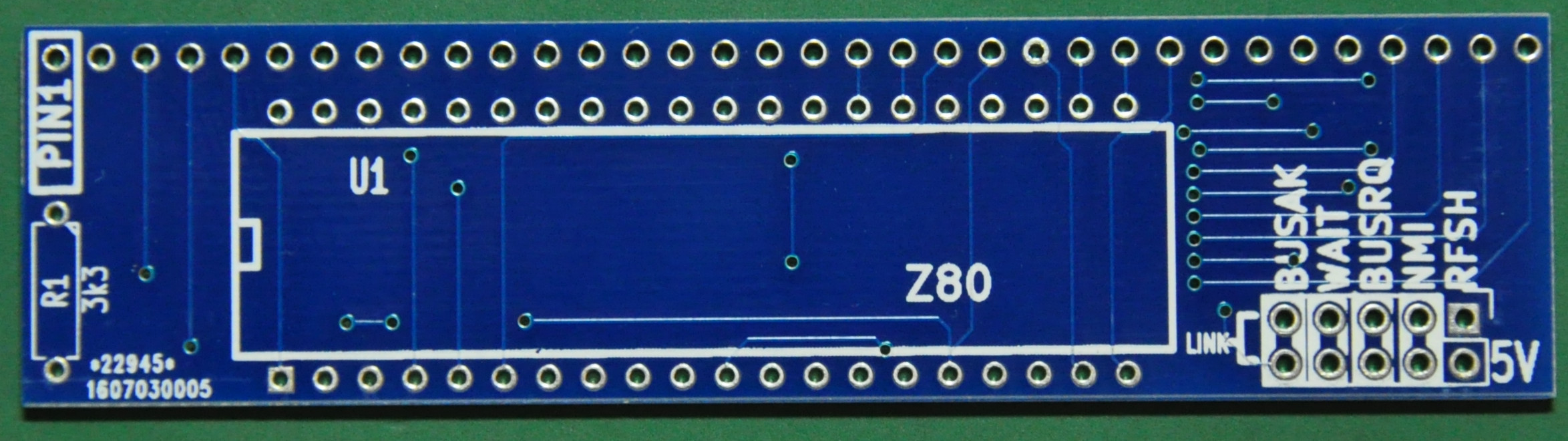
The board quality is the same as the clock module, very straight forward. Now, just start soldering the board.
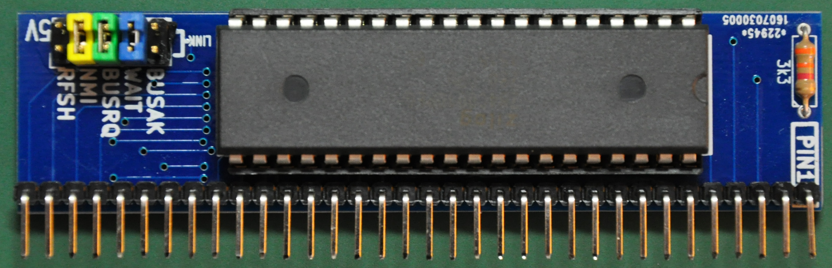
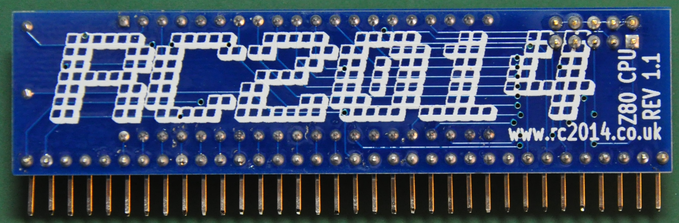
Above is the finished board. As always I have cleaned up the board with flux cleaner. I took some time on assembling this board as I want to make the finished board nice. According to the manual, we have to link the WAIT, BUSRQ, NMI to 5V. I have soldered pin header to the footprint in case want to use those signals on future projects.
ROM Module
The next module will be the rom module. In my kit that I bought included an Atmel AT27C512R rom chip. It is a 64k rom chip. The rom is divided into 8, so it will be visible for 8k in one time. So we have 8 selectable banks but only can select one banks at a time.
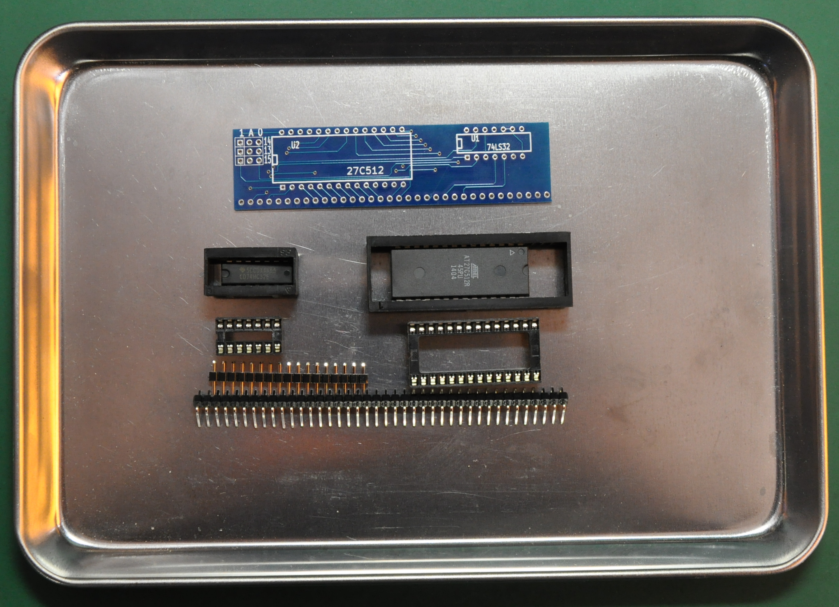
Here is the components included with the kit for ROM module. Not much components to solder at all.
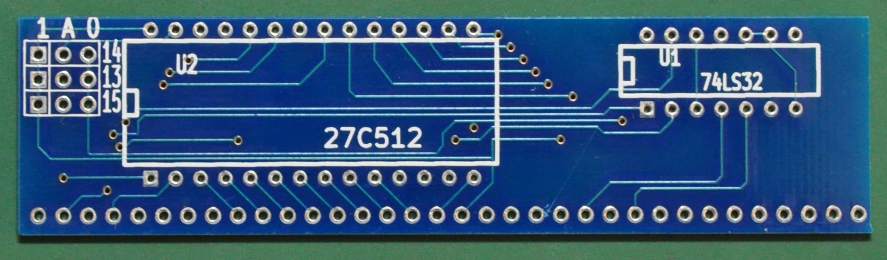
The pcb is as usual, very good quality.
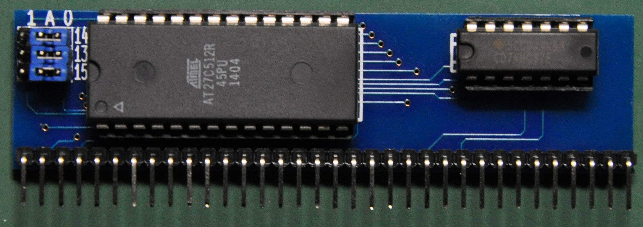
Here is the finished board. I have set the jumper as in the manual so it should run Microsoft Basic when we power up the computer then. One thing that I have discovered is the included ROM chip. It is a one-time programming chip, thats mean that we can’t reprogram the chip anymore. So we need to provide another ROM chip in order to use other software like monitor program etc. I want to use monitor program for my assembly learning so I have swapped the ROM chip with mine. I have set the rom with the default Microsoft Basic on bank1 and monitor rom on bank2. So I can switch those banks with the jumper, Microsoft Basic is on address 0000-1FFF, my monitor rom is on 2000-3FFF.
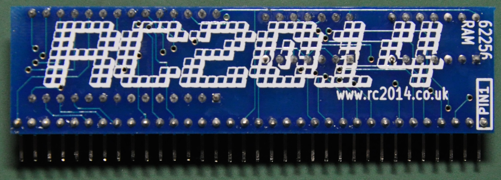
RAM Module
The RAM module provides 32k of RAM to the computer. The components just have the RAM chip and two glue logic. It is very straight forward and easy to solder.
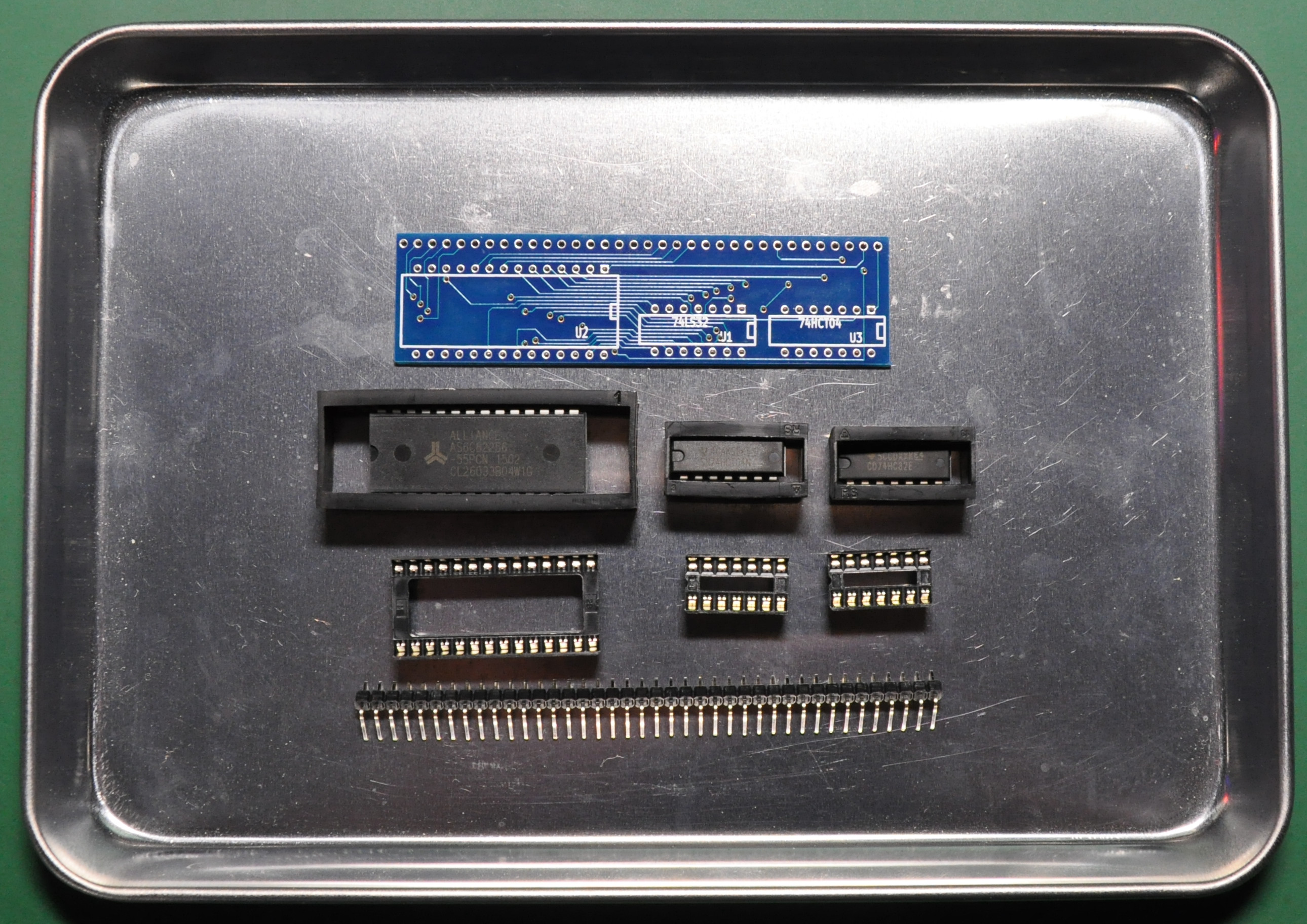
These are the components, IC sockets, the RAM itself, 74LS32 and 74LS04 for chip select works.
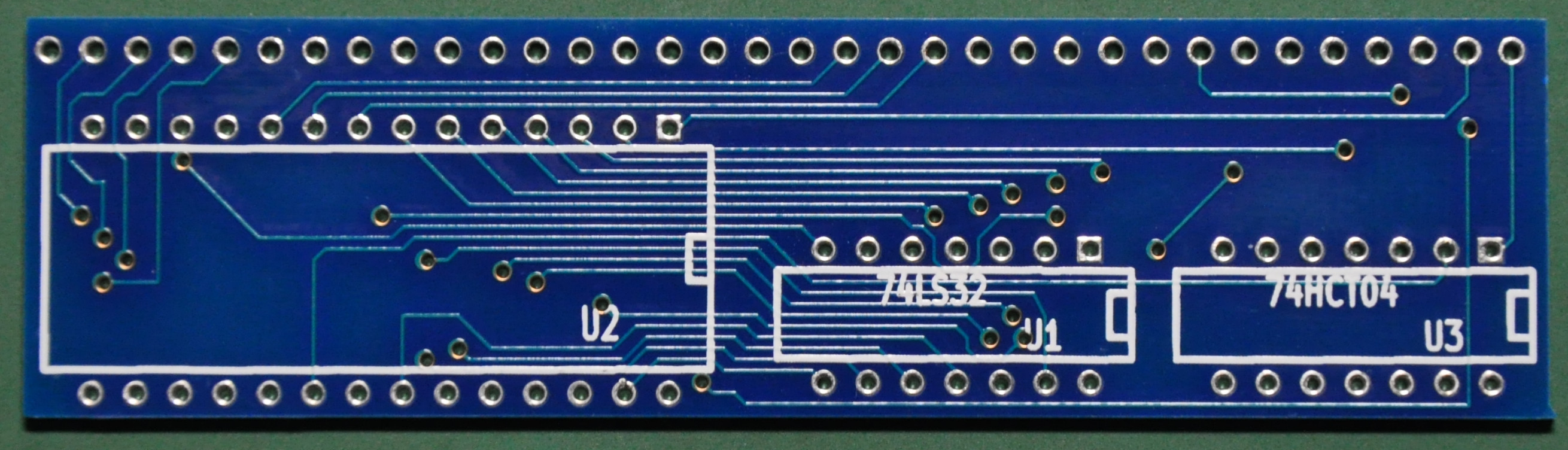
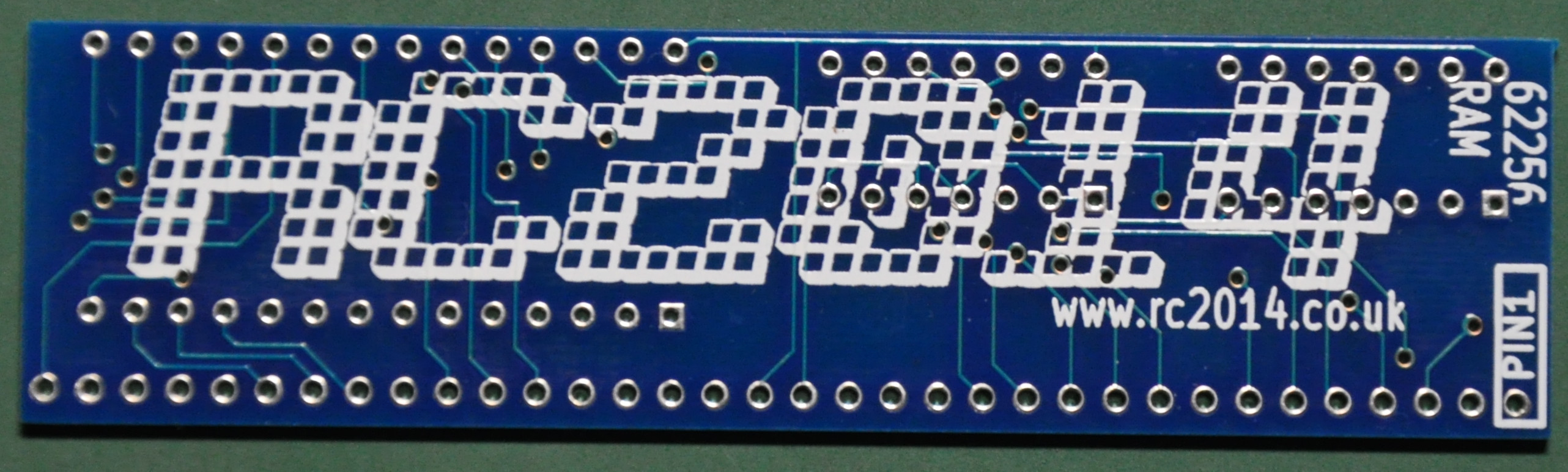
The included pcb is very nice, I have no problem with the soldering process although it is small.
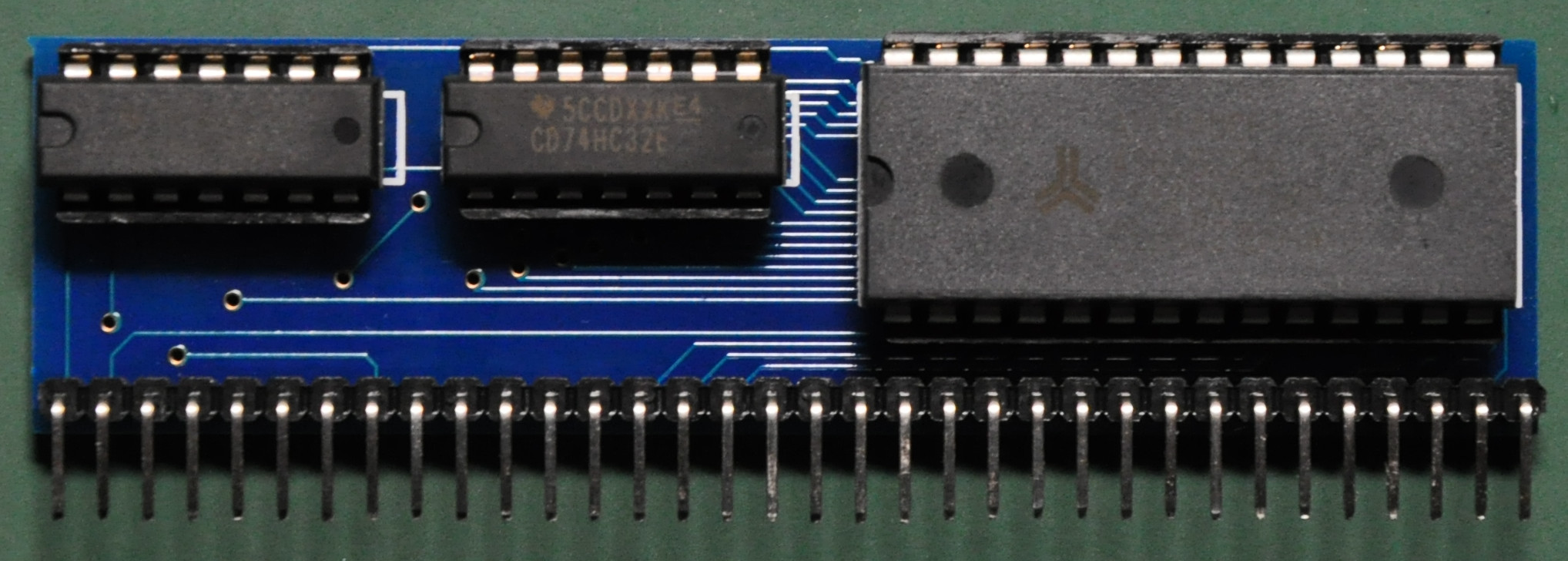
These are the finished boards. I have washed the boards with the flux remover.
Serial I/O
The last module is the serial I/O module that provide the computer serial communication interface. It use the 63B50 UART chip. In the kit that I have received included the Hitachi HD63B50P. I have bought two of these module, one that included the option of the MAX232, a few pump capacitor and DB-9 connector to implement RS232C level serial.
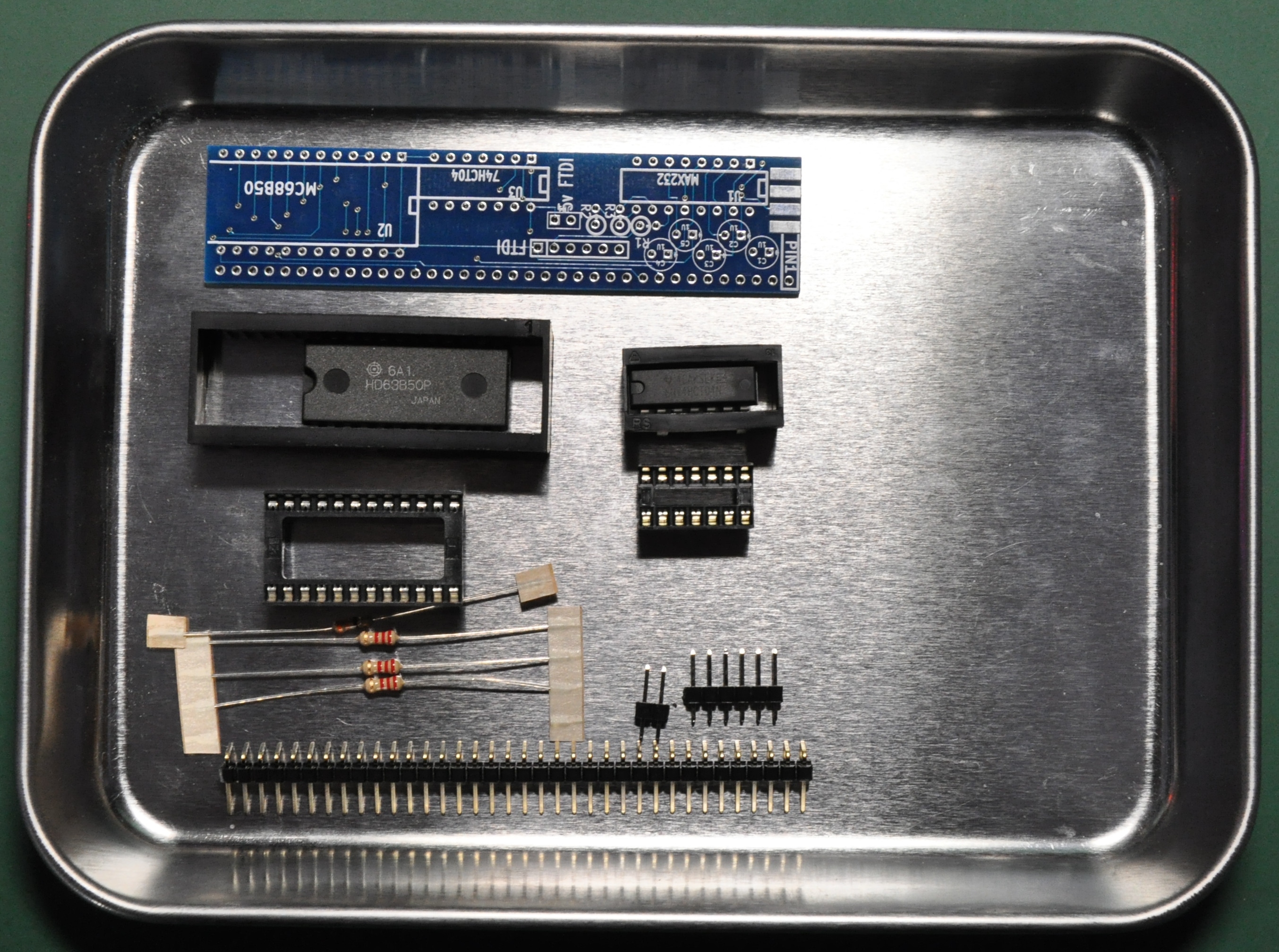
Here is the components included. Nothing difficult to solder then.
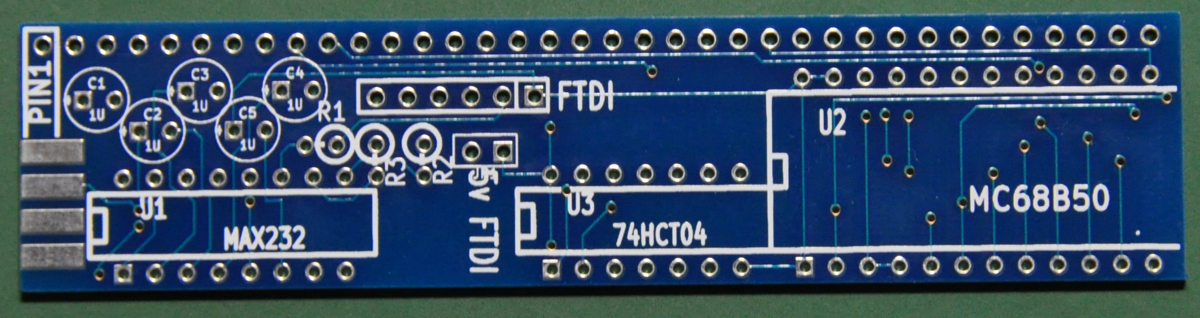
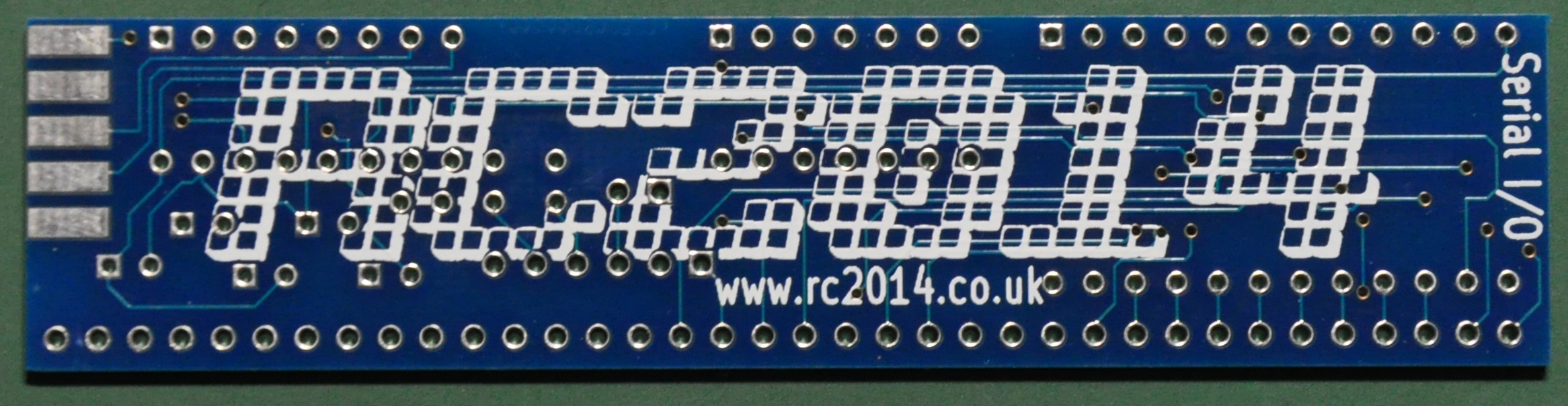
As same as the other pcbs, a good quality boards provided.
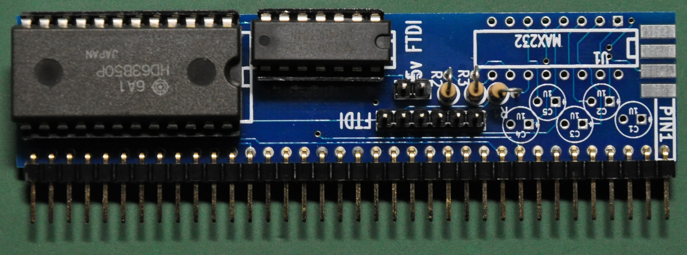
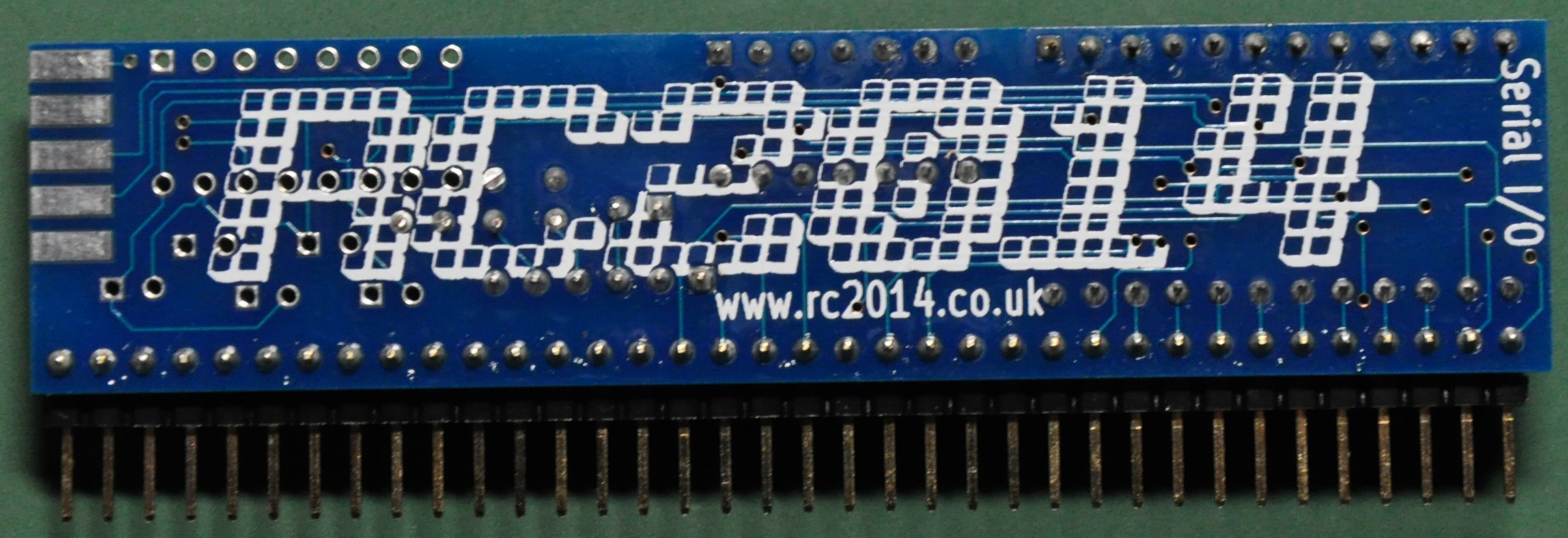
Here is the finished board. The above board needs the USB-TTL serial converter to connect.
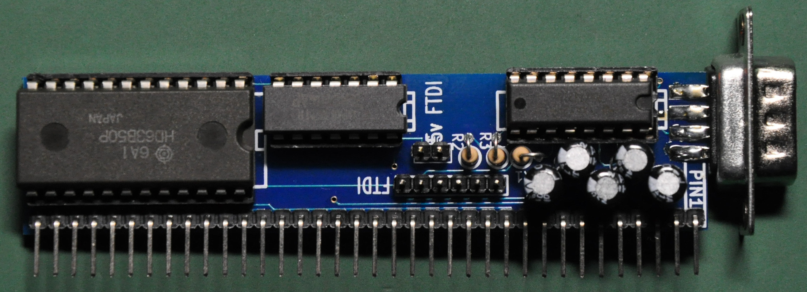
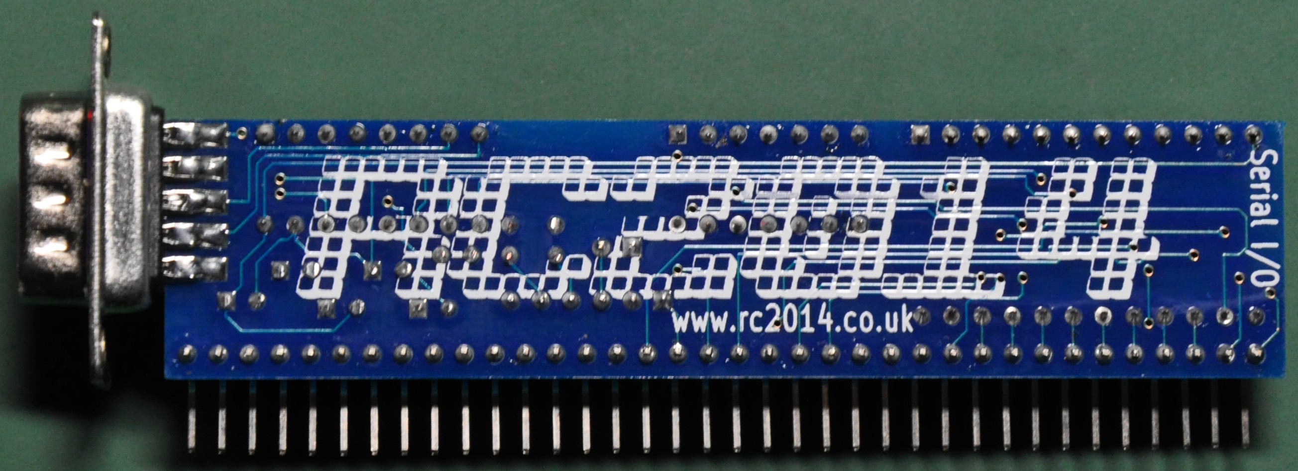
The above is the another board that I have implemented the MAX232 to provide RS232C level communications. One issue that I am facing here is, when the module implemented with the MAX232 chip. we can’t use the TTL header to communicate with the host computer via USB. We can receive the data but can’t transfer back to the RC2014. I will update this when I know something about it.
Initial Power Up
Now it is time to do the initial power up to see if everything goes right. I connect the serial usb adaptor to the RC2014 and host computer, setup the serial to 115,200/8/N/1. I use TeraTerm for the terminal program on Windows 7.
Well it looks like everything goes fine without leaving any ‘Magic Smoke’. As we give the power to the backplane, the led will lid, then after we hit the reset button there is something appear in the serial console.
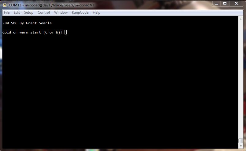
At first power up session, it will ask to warm or cold boot.
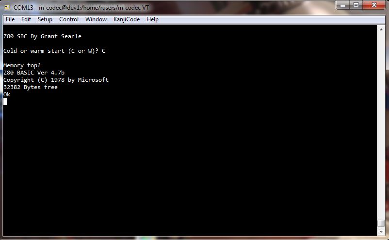
Finally, the MicroSoft Basic. Let’s make some test on basic programming.
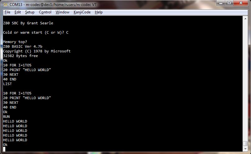
It looks like basic runs as we expected and it means that we have successfully build the RC2014 computer.
Conclusion
That’s all for the module build log. I will update when I have implemented something new on hardware or software. Here is the picture of the finished computer.
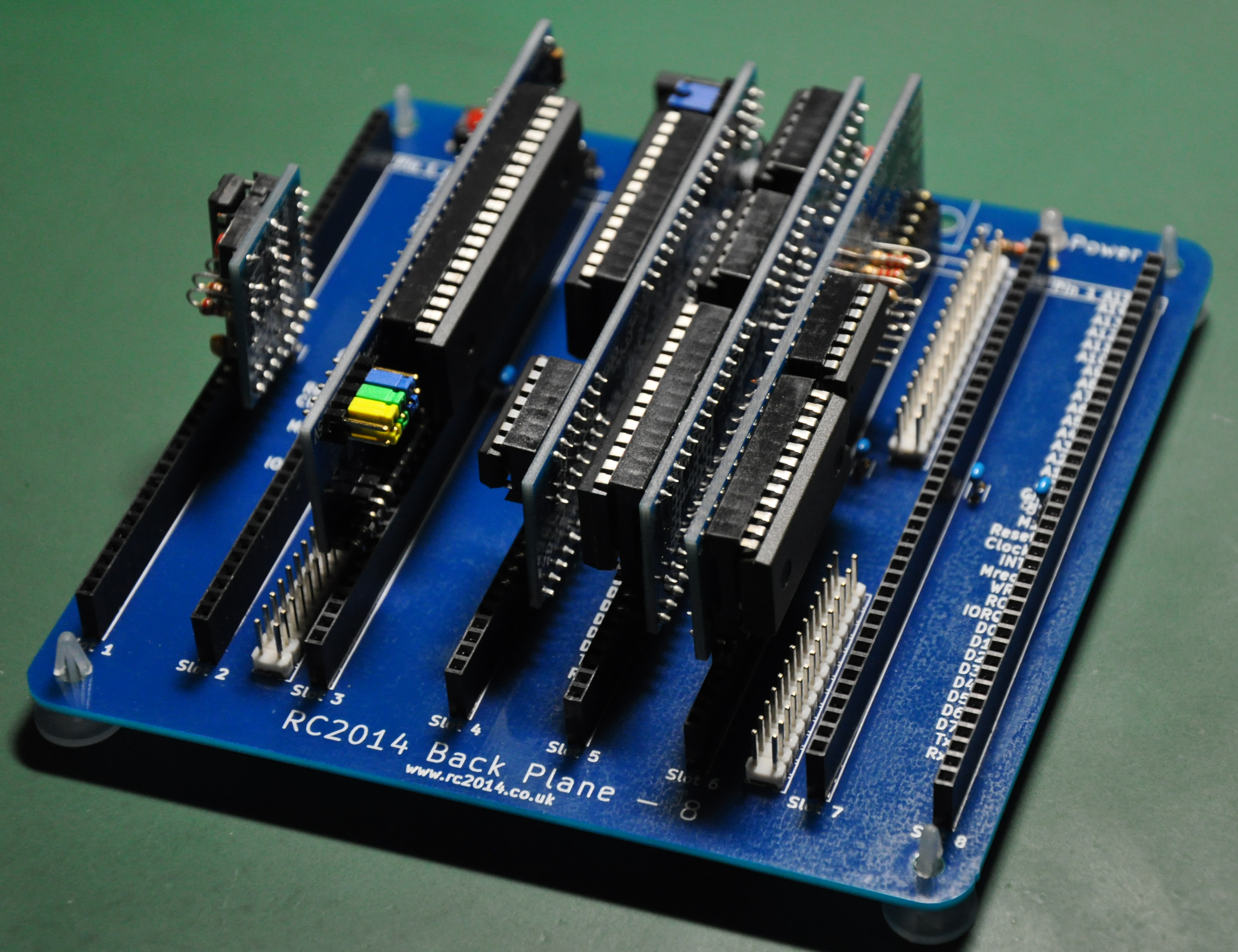
I am very happy with the build. The computer itself is well designed and I am very interested with the backplane design. I am planning on learning z80 assembler, writing my own bios and monitor program. I’m also planning on implementing third party module boards like Dr. Baker’s boards, and finally make my own boards in the future.
I will update any progress that I made when ready.
